ESC.VTOR
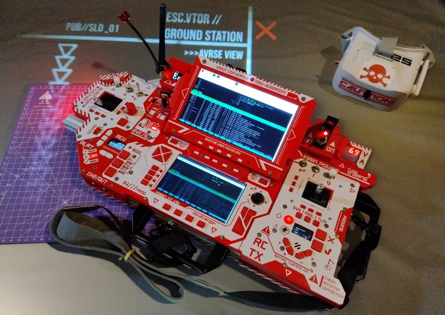
ESC.VTOR ("escape vector") is a "most-in-one" solution for overt unmanned vehicle ops that comes with: two screens, Raspberry Pi 4 SBC, plenty of ROV controls governed by Edge-TX firmware, Micro JR transmitter bay, macropad-like input system, triple channel analog video chain, local OSD, RGB torch, tripod mount bracket and a robust aluminum extrusion frame to carry it all through any mission.
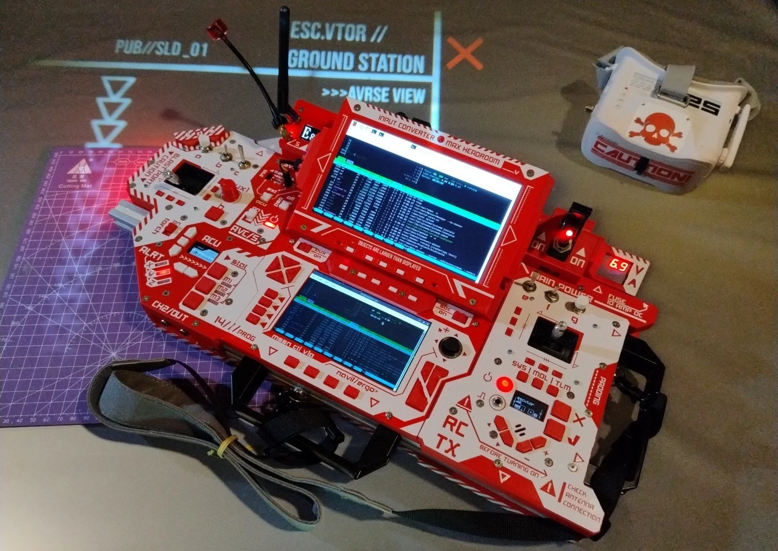
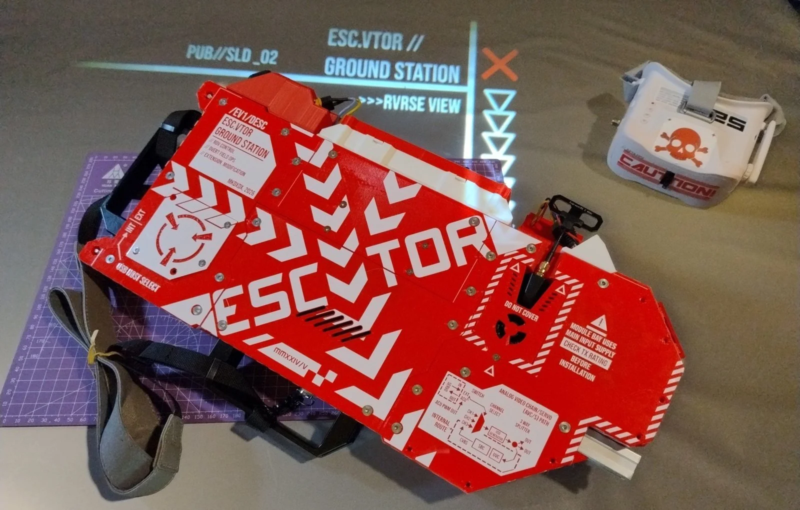
Double Vision
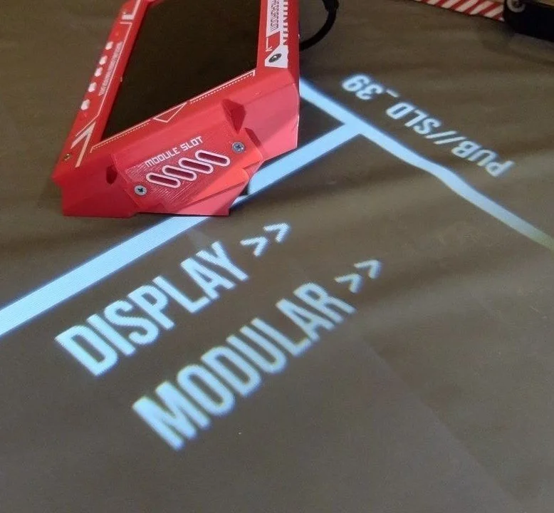
While the primary 5" screen can focus on telemetry display, the auxiliary 7" screen module can be either used as-is — connected via HDMI to the system — or switched to analog video chain output for that extra low-latency visual link.
Why it's called auxiliary, despite being bigger? Because it can be detached and used standalone, freeing connections for other tasks.
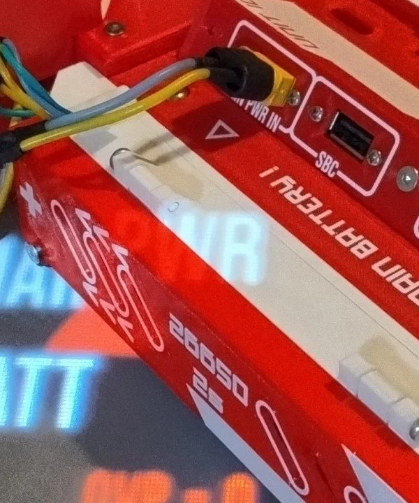
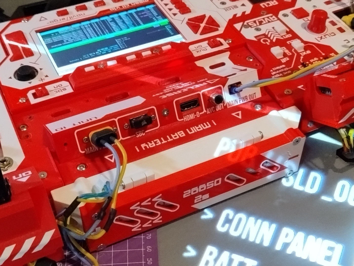
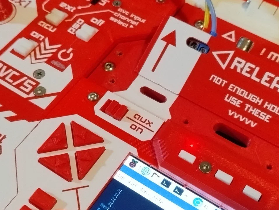
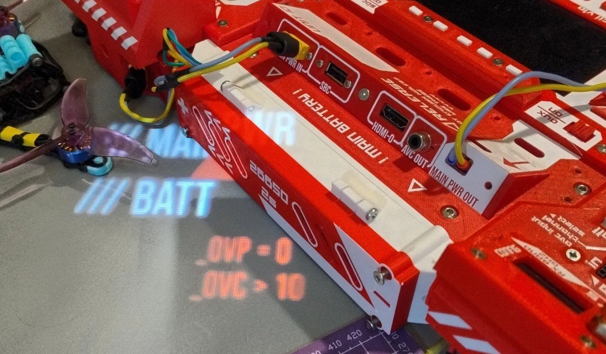
And there are plenty of tasks for the connector array underneath — USB directly to SBC, HDMI-0, analog circuit output, auxiliary power output, and of course main power input.
With a flip of a switch, auxiliary power output can be shut off to conserve energy.
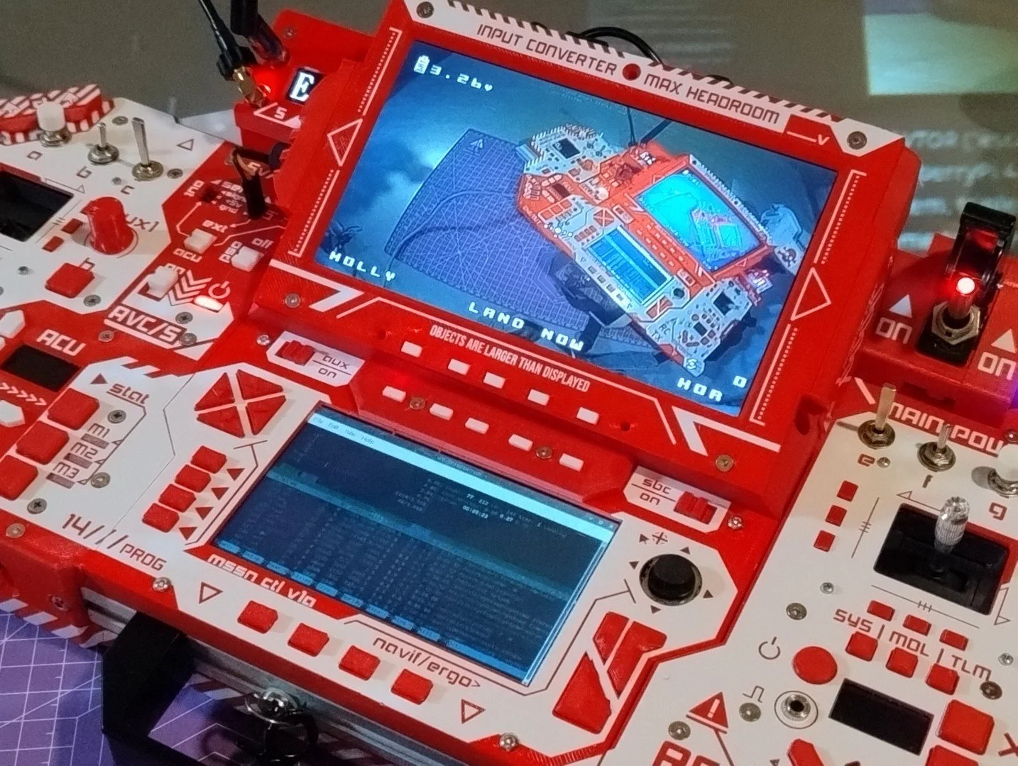
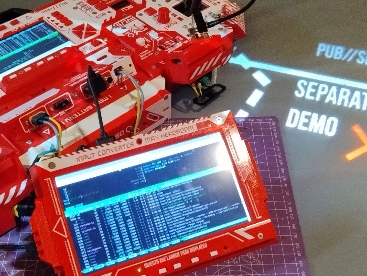
Triple Reception
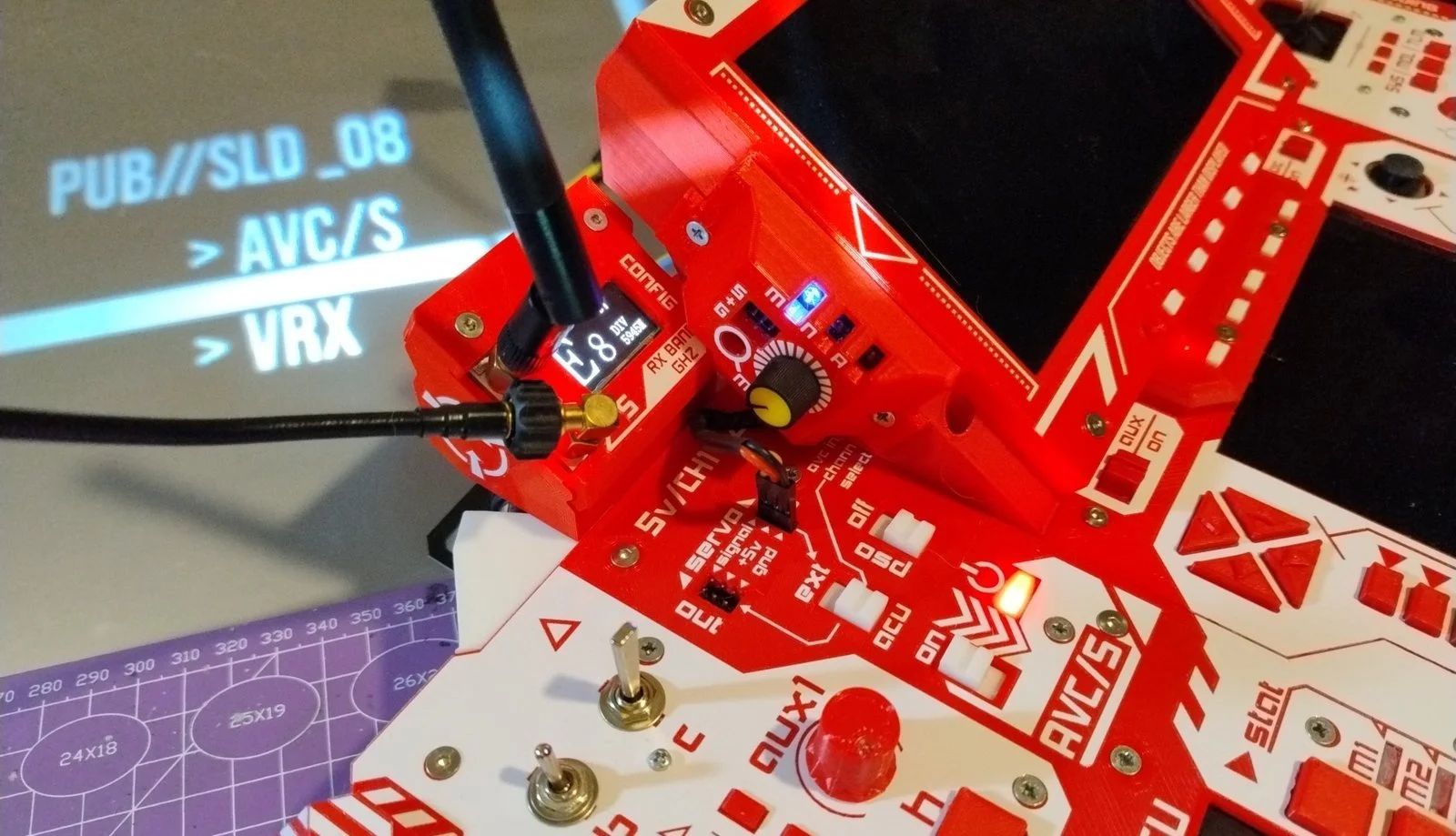
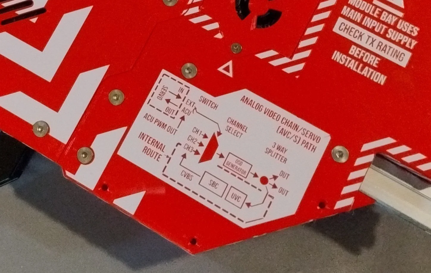
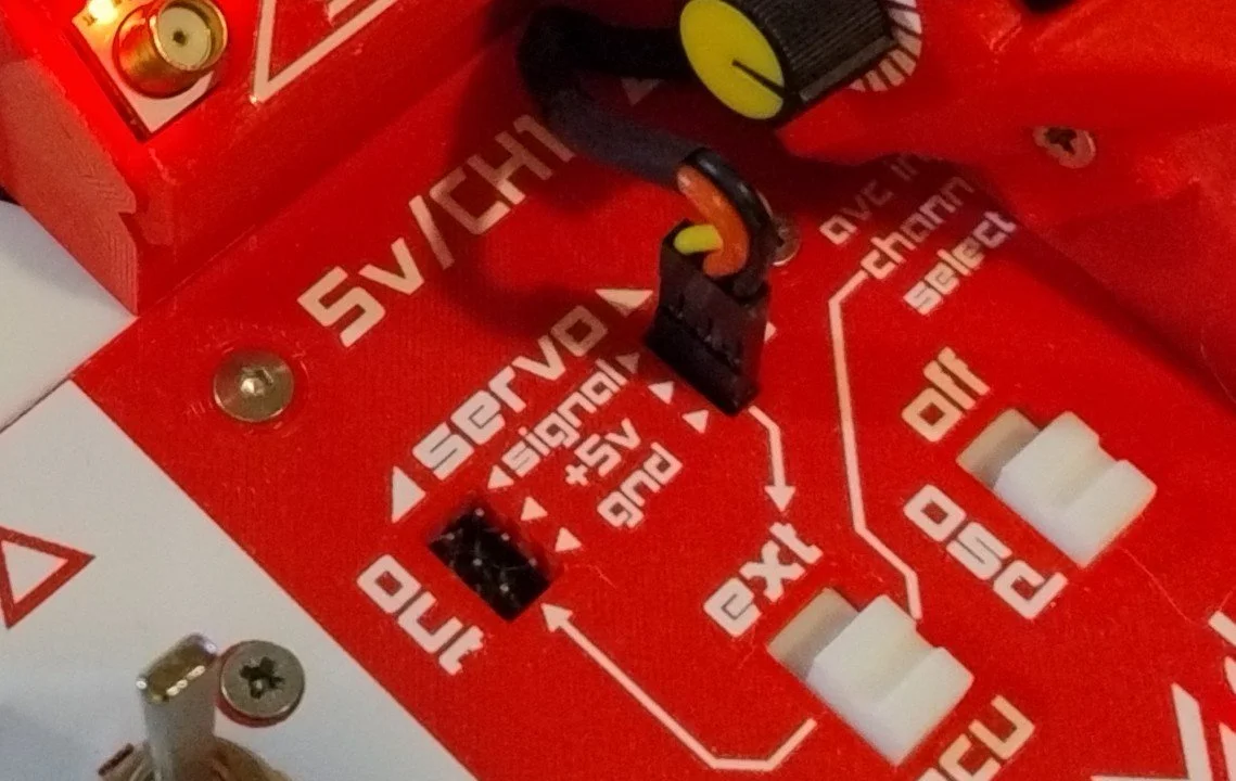
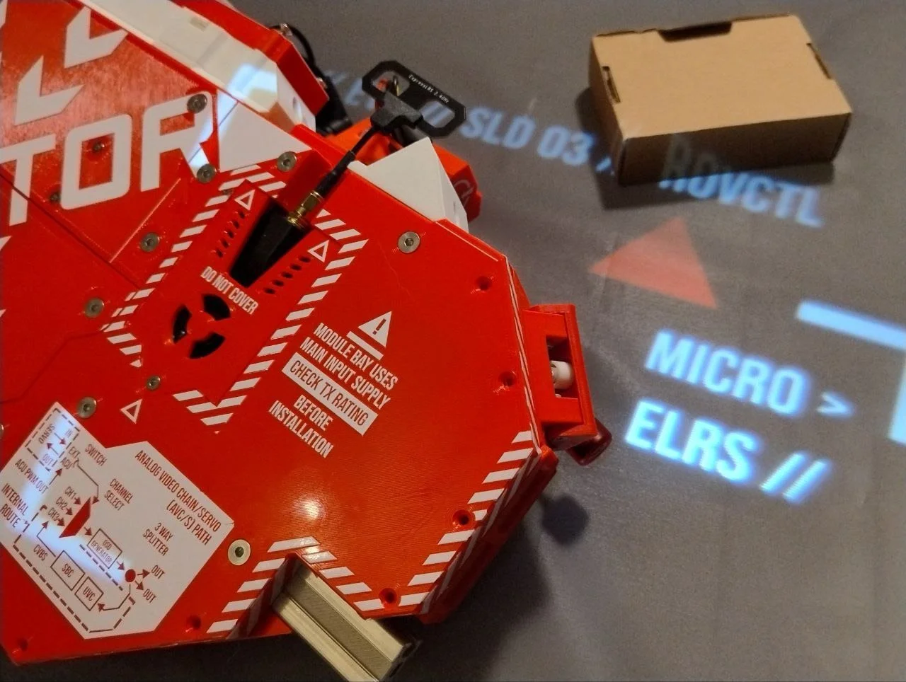
Analog video chain selects one of three video inputs, pipes it into an OSD generator, then splits it into three outputs. The circuit expects a 50 Hz servo pulse signal that can either be taken directly from the built-in macropad unit (ACU) in servo-multiplexer control mode, or piped in from outside — e.g. from a servo consistency tester.
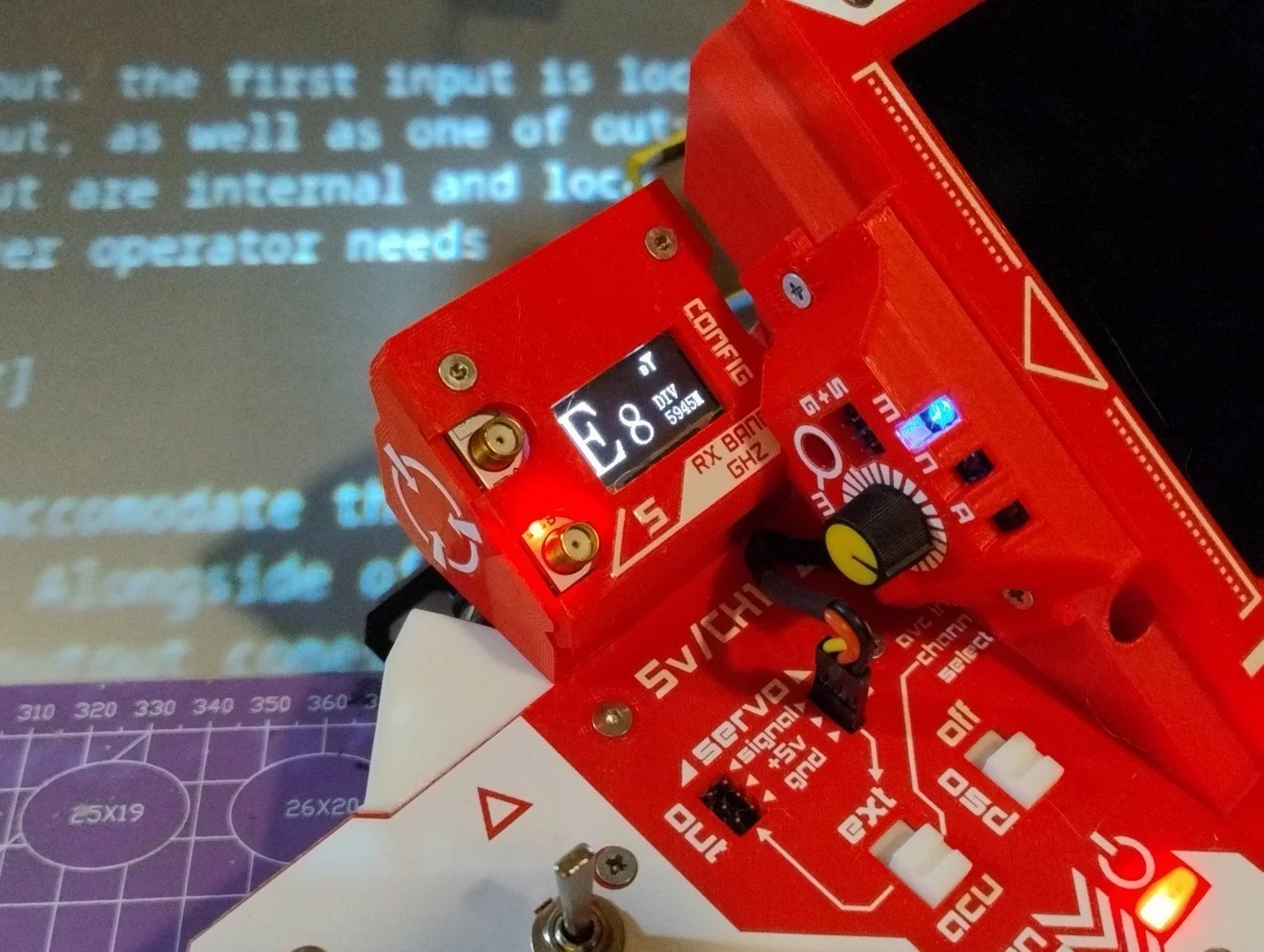
This process is managed from the AVC/S control cluster.
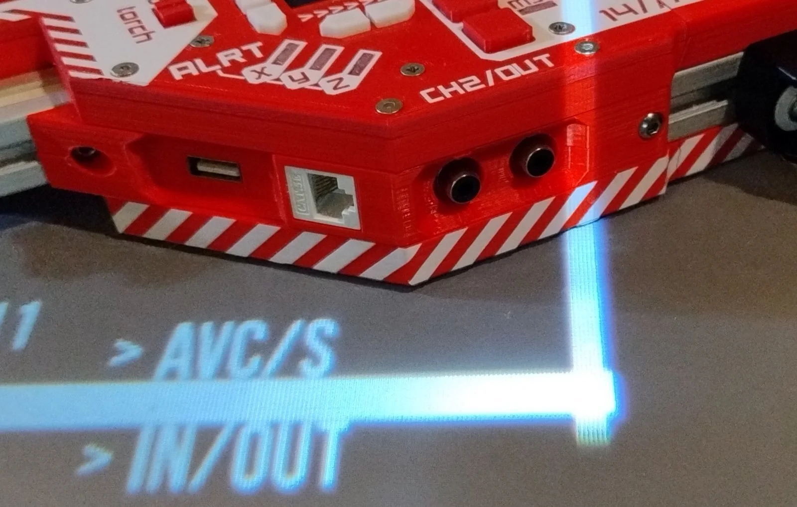
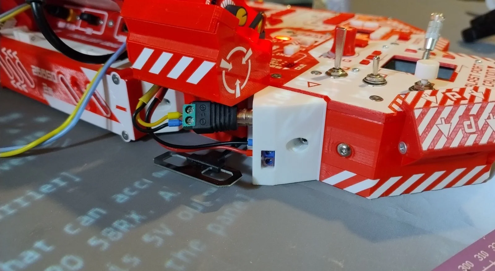
Technically only two inputs and outputs are broken out: the first input is located on the back rail and used for VRX, while the second input, as well as one of the outputs, is located on the front left rail.
Alongside the input connector there is also a 5V output to power the receiver. This 5V comes from the video chain power rail and is controlled by a slider switch on the panel — so you can shut down the whole video chain at once.
Third input and output are internal on the video chain board — wire them out wherever the operator needs. The complete circuit is described on this handy marking.
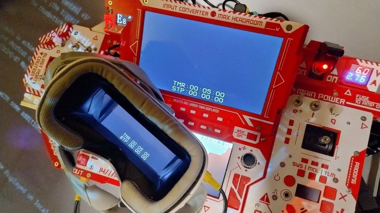
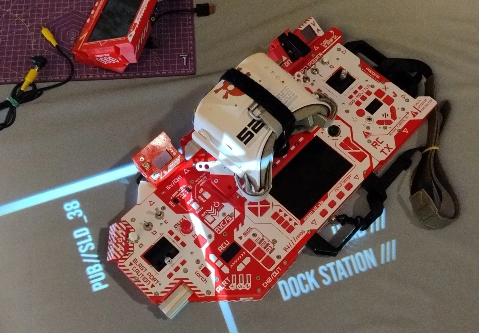
Base configuration also includes a VRX caddy that can accommodate the popular "attach to goggles" VRX module format, like this Eachine PRO 58RX.
Versatile Essentials
Built-in controls are stripped down to a set of configurable, macropad-like inputs:
• a row of 4 buttons under the main screen — F1–F4 by default
• a column of 4 more buttons to the left of the screen — PgUp, Home, End, PgDown by default
• directional buttons — arrows by default
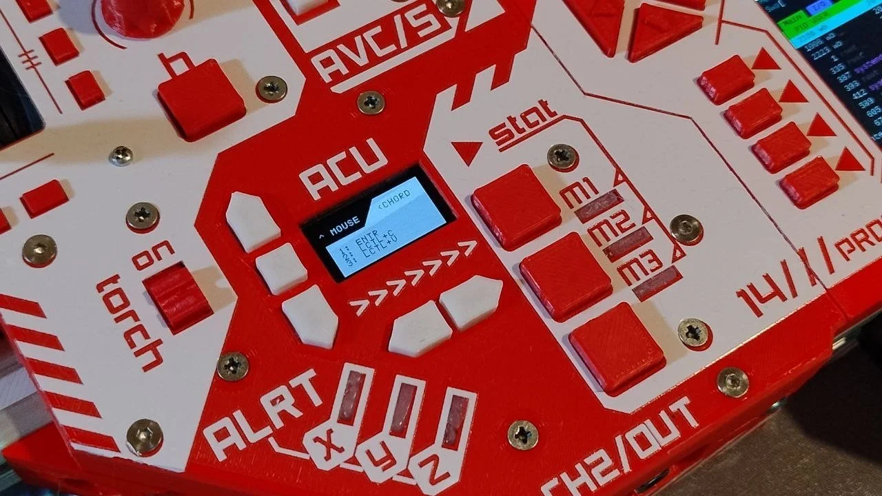
• 3 macro buttons — Ctrl+C, Ctrl+V, Ctrl+Alt+Del by default
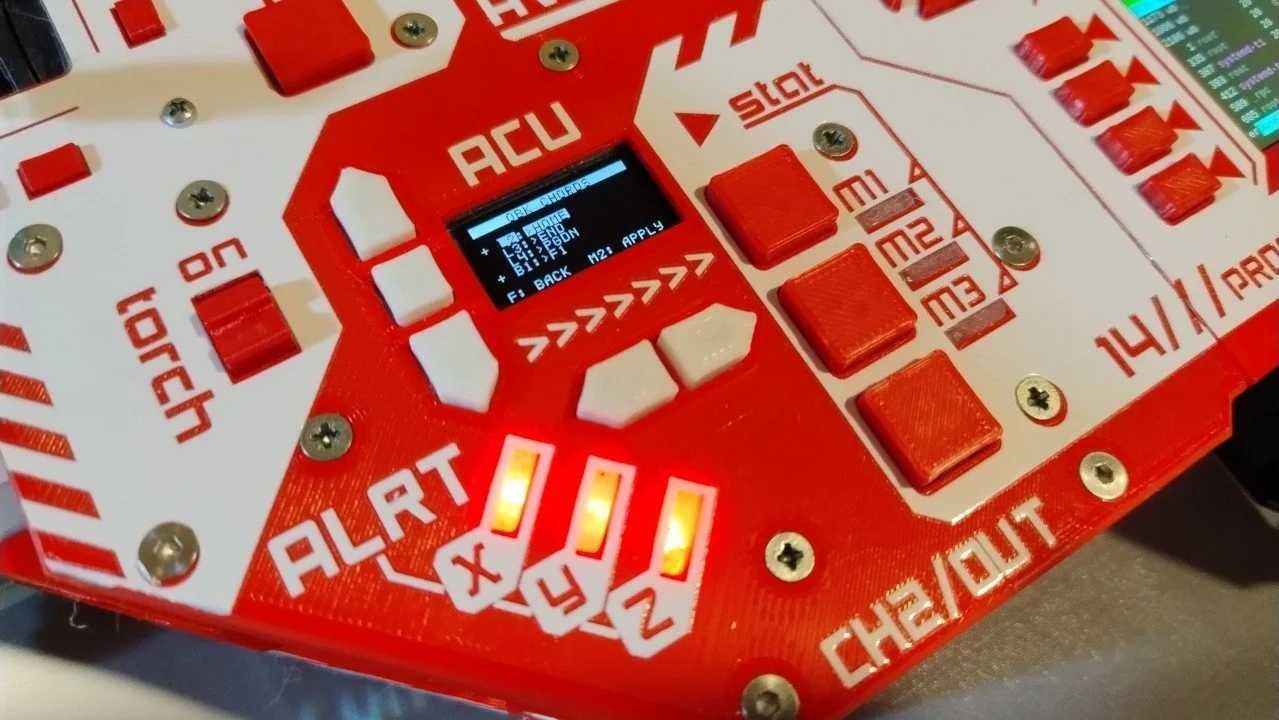
• 3 LEDs that show if macro-button latch mode is enabled, or for other signalling
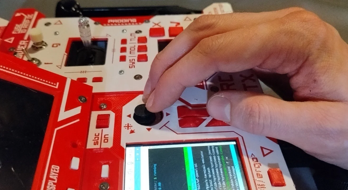
Additionally, there is cursor control via thumbstick, accompanied by a button trio for left (the biggest), right (smaller), and middle mouse buttons directly under the stick.
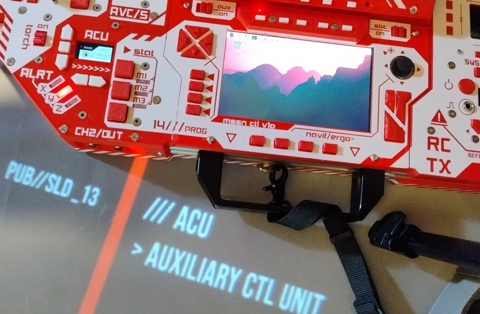
The versatility of inputs comes from the ACU (auxiliary control unit), which assigns keystrokes and shortcut combos onto the buttons above. Want to Ctrl+V whatever you just Ctrl+C'd? Maybe a casual Ctrl+Alt+Del now and again?
ACU Extras
Stopwatch and countdown — can run in the background and display on local OSD. Stopwatch has lap tracking. Countdown lights a LED at zero.
Servo-multiplexer control — 3 configurable duty-cycle presets, mostly used to control the video chain multiplexer; output is also broken out on the VRX control panel. Test ROV parts like ESCs and servos, or drive an antenna actuator. Automatic duty-cycle sweep and extra pulse parameters are WIP.
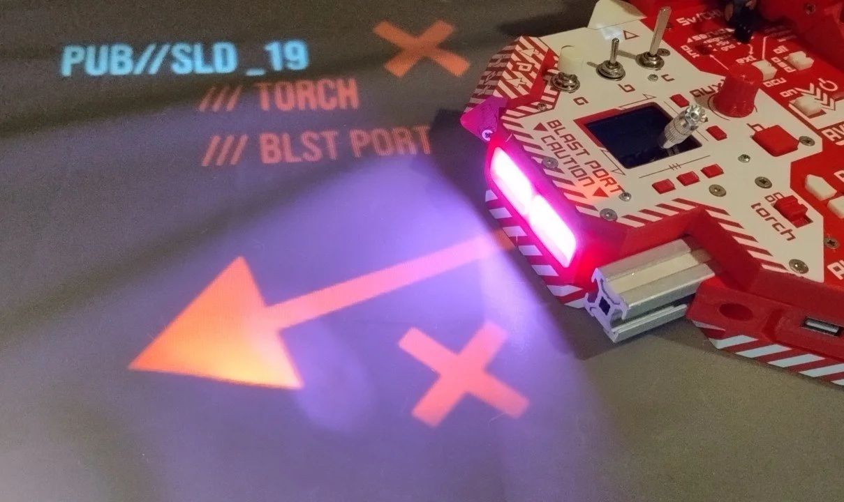
Torch mode selector — party-colored blink modes, plus a proper colored (or warm white) torch for dark environments. Can also emit SOS at two speeds. Per the decals: torch has its own on/off switch near the ACU.
Focus on The Edge
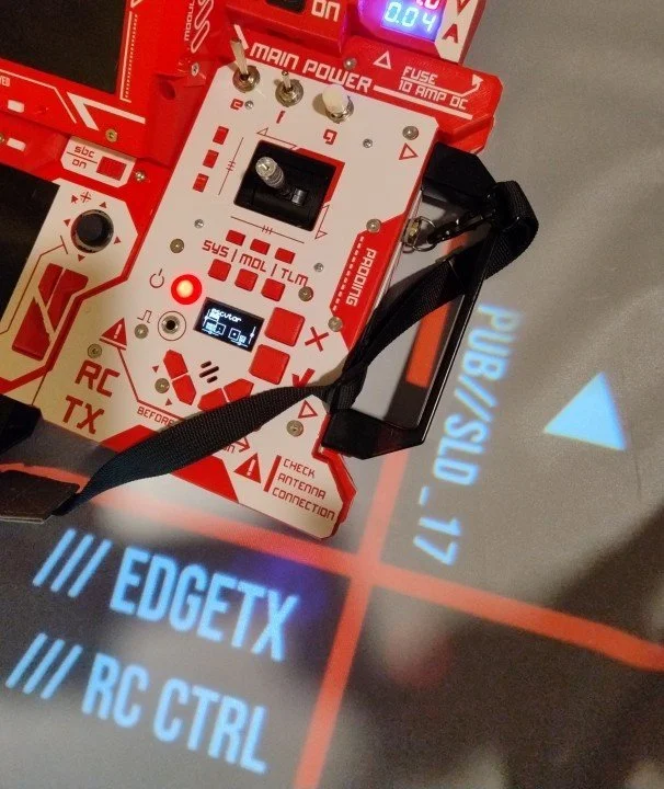
The unit won't be ROV-aimed without sticks, switches (2-pos and 3-pos), momentary buttons and trims — all routed here, where an Edge-TX firmware port runs, reads the controls, and sends signals into the Micro JR bay where the ExpressLRS module lives.
Obviously you can slot in any compatible module, not just this Happymodel ES24TX Pro — as long as it uses 6–9V (supply voltage is taken directly from the unit's primary power input), supports CRSF, and physically fits.
And being a full-fledged Edge-TX powered controller, its feature set can be looked up on the Edge-TX project page itself — and it can connect to a host over USB as a joystick for sims and whatnot.
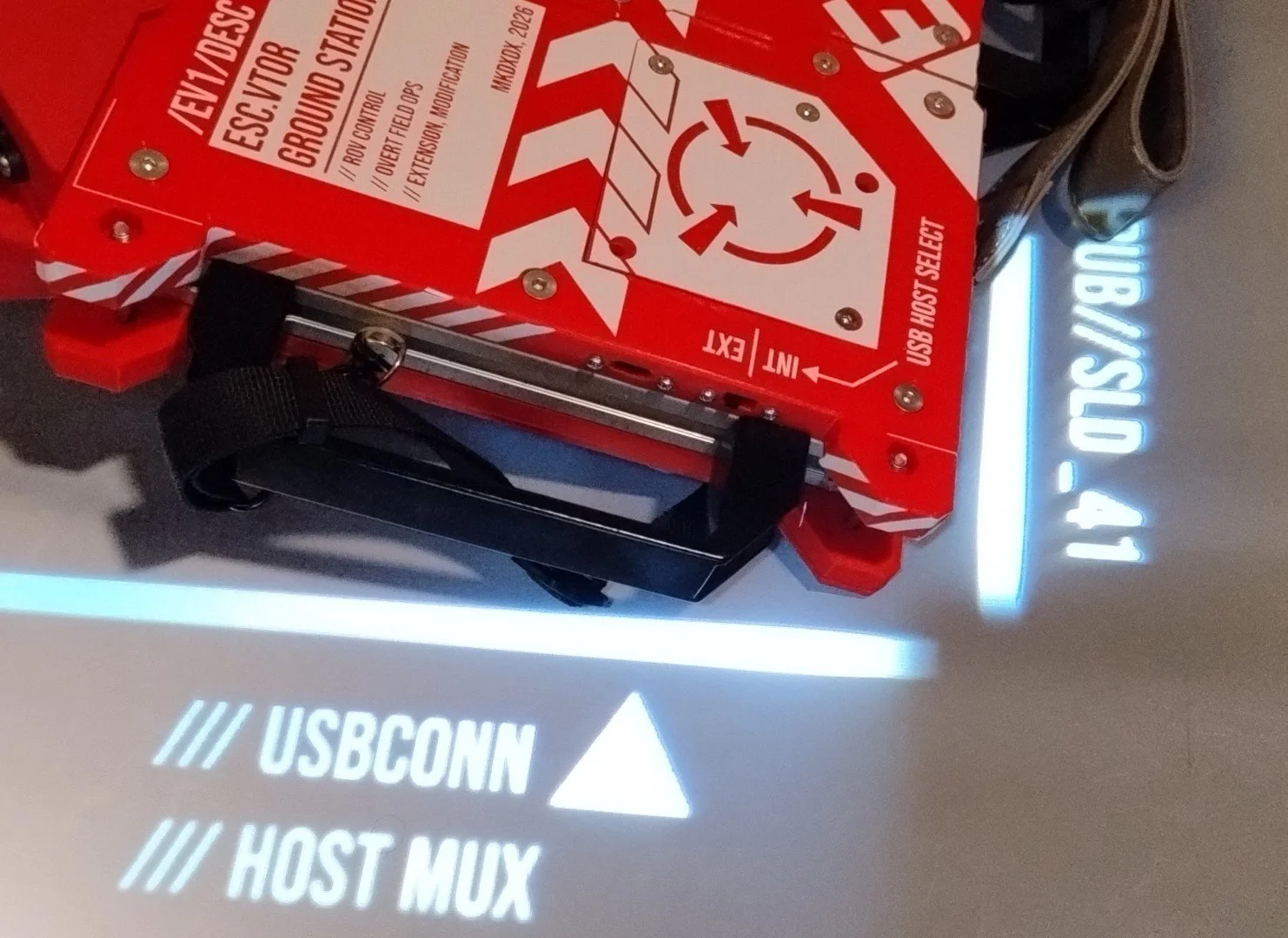
Thanks to the USB multiplexer, ETX connection can be manually selected between internal (to RPi) and external (your sim PC).
A remark about the ETX port itself — the board runs on yet-to-be-public ETX v3.x, and is not part of the official repository yet. Stay tuned: one day the port will see the light of day, once it complies with repo rules and has been fleshed out a bit.
Though even in this state it is enough to control a little drone:
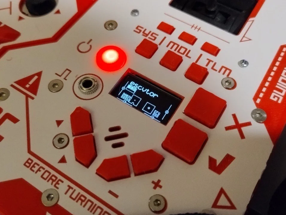
Trainer jack (pulse glyph under the power button) and voice/sound are WIP — it can act as a student remote (PPM out) and do basic alert beeps though.
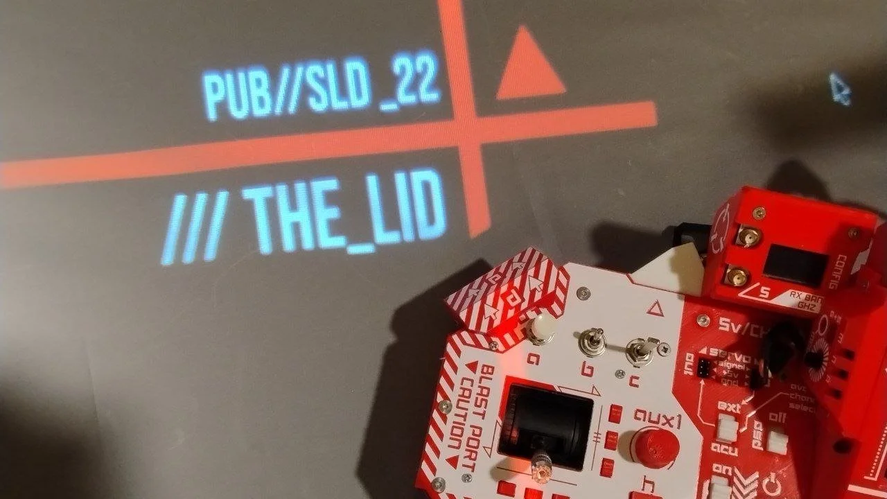
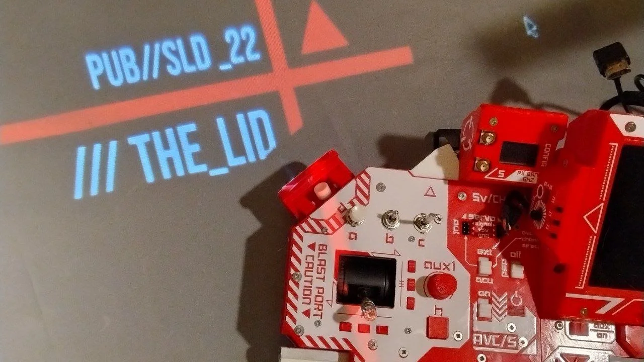
For the most important functions, there's a dedicated button with a magnetically locking lid.
The Powerhouse
The power system is kept simple: no integrated batteries or charging circuits. That leaves more room and more choice — provided you can offer a pack yourself.
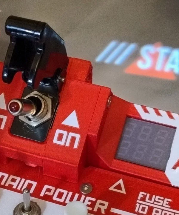
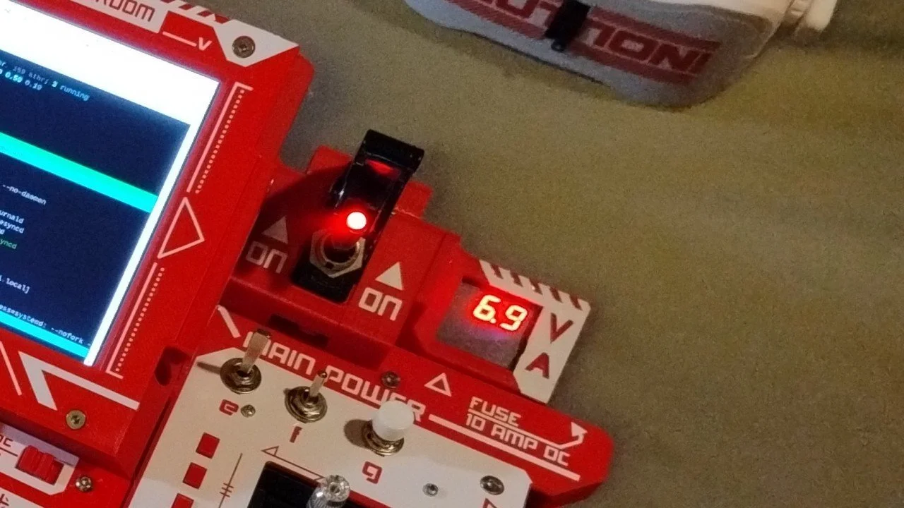
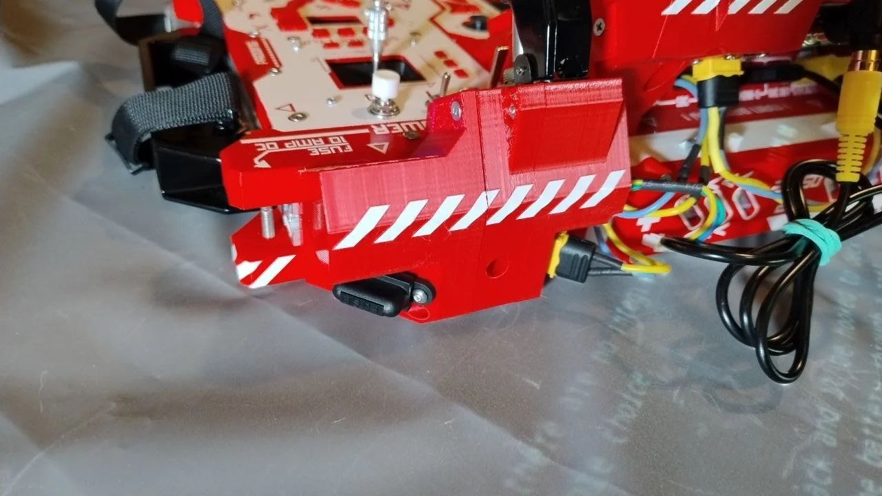
The current configuration expects power from a 2S Li-Ion pack hooked to the deck's XT60 directly. It is much safer to route the battery through a rail-mounted switch block — big LED-equipped missile switch, 10A fuse socket, and VA-meter window.
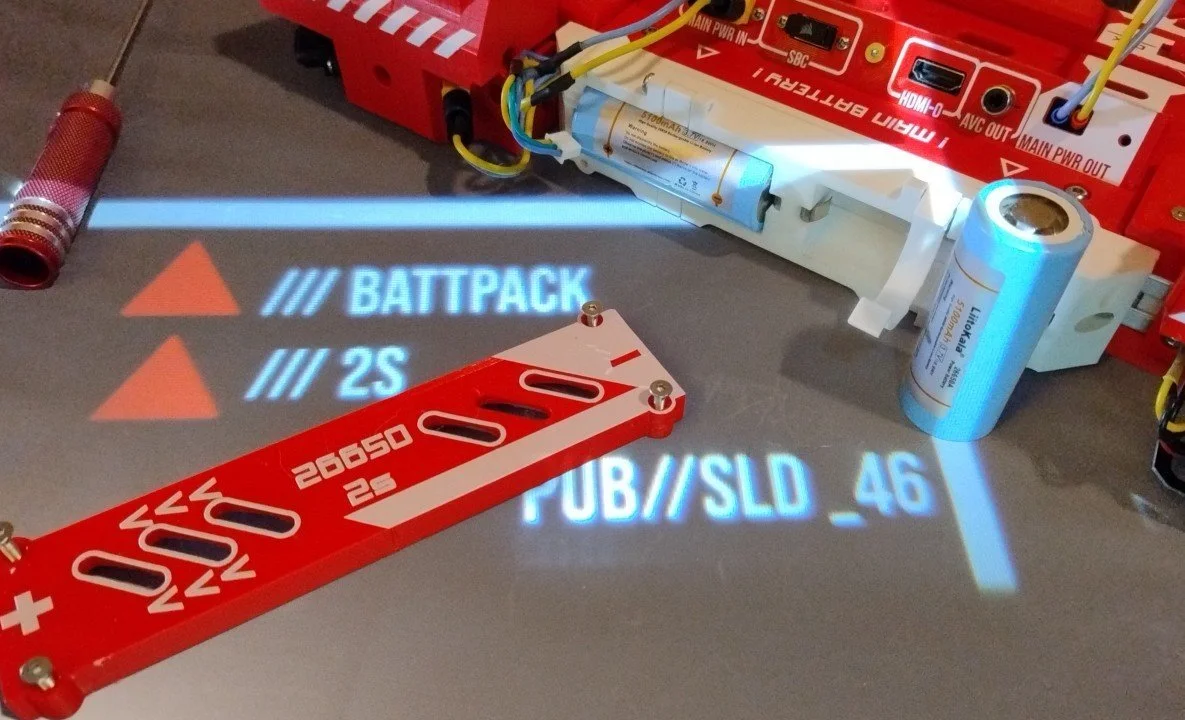
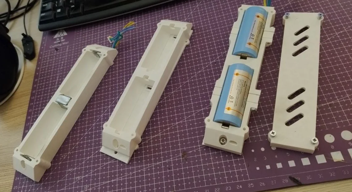
The battery pack houses the cells with a main output and a balancing connector. The pack itself can be opened to swap 26650 cells for a pair of new ones.
The converter array can accept voltages higher than a 2S pack provides (LM2596HV modules), but because the auxiliary screen step-up expects under 12V and ELRS modules generally top out around 9V, this configuration is limited to 2S input.
Discreet Flexibility
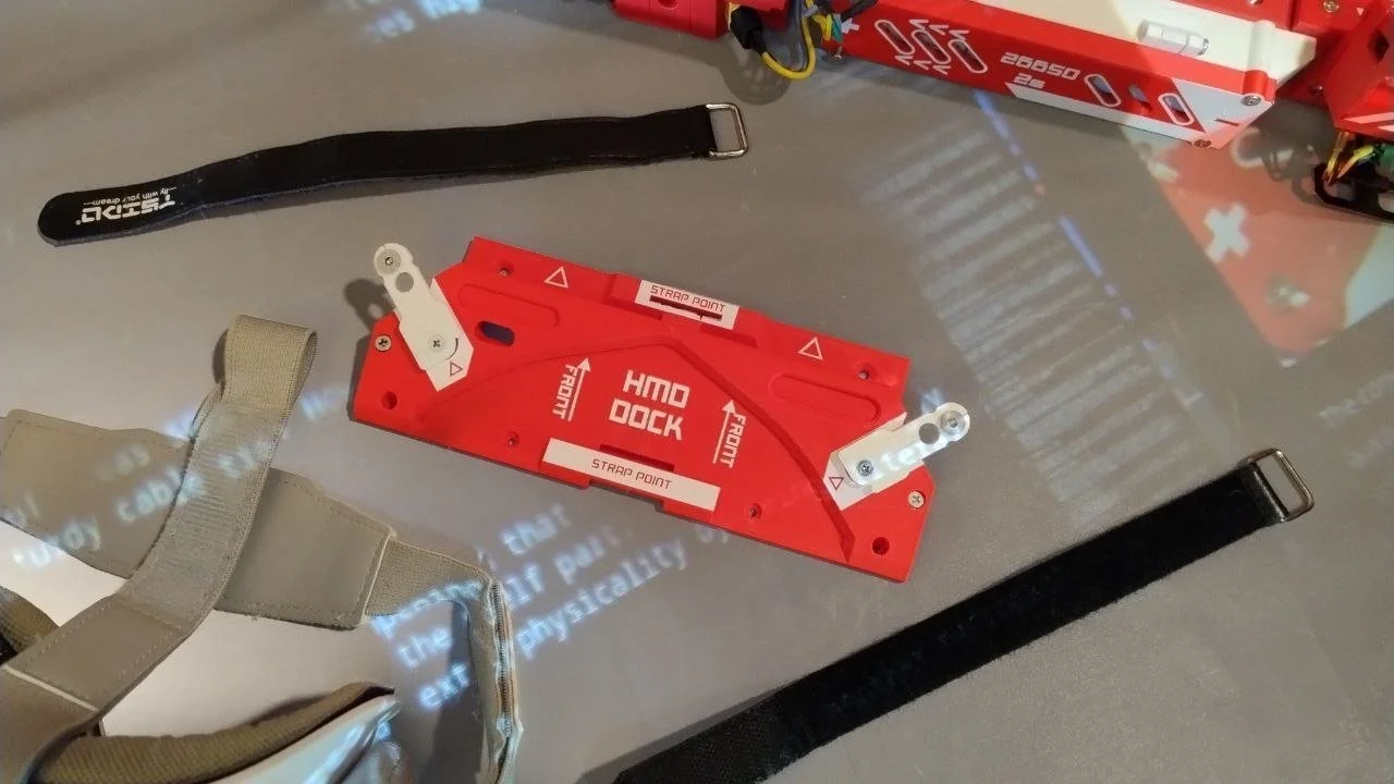
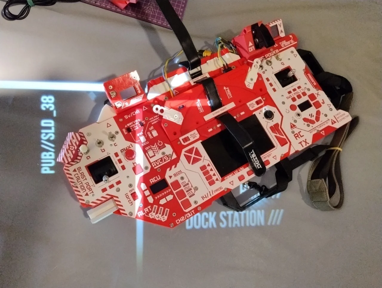
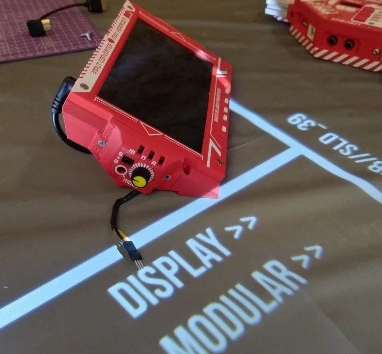
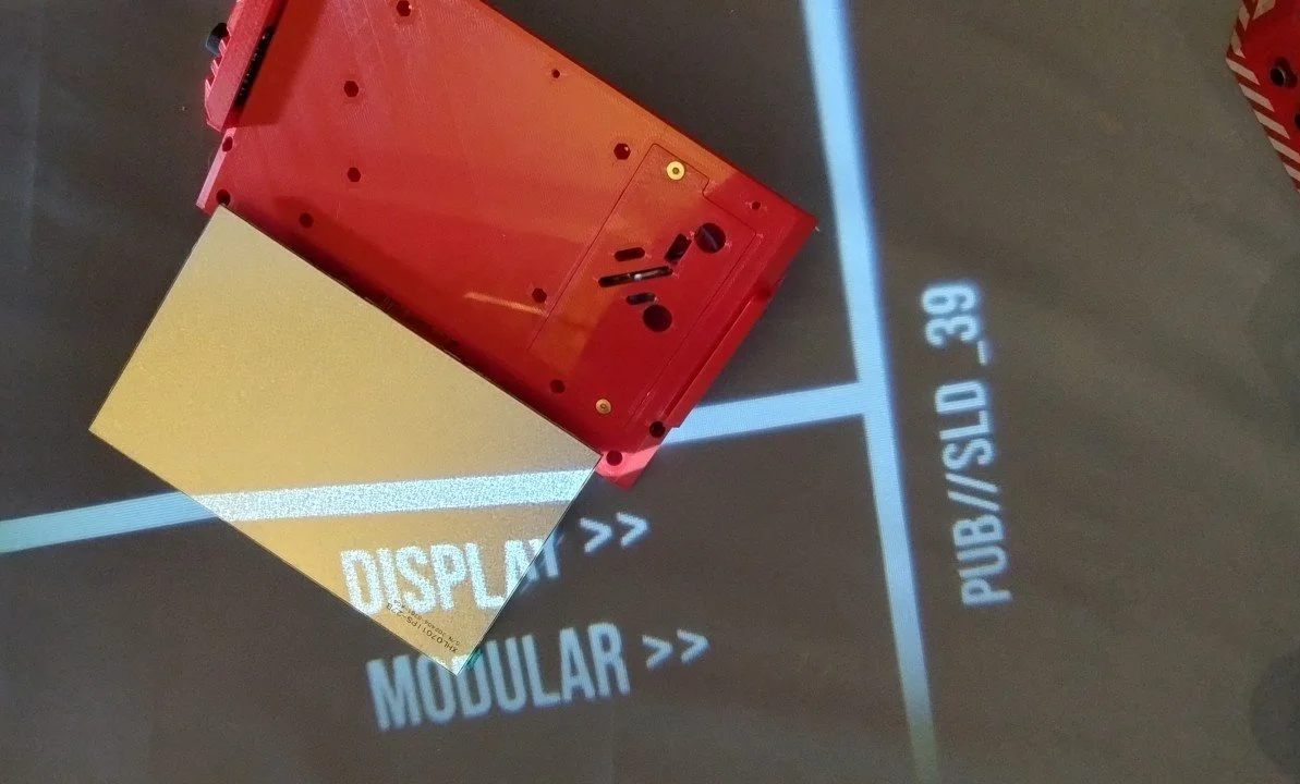
The unit does not lean hard on modularity, but some things reshape for the task. The display can detach to expose a low-profile connector panel, and there are plenty of places to attach something else — bigger display, cable ties, or a dock for FPV goggles.
The auxiliary display features two mirrored openings that can house simple modules like this servo consistency tester — an off-the-shelf part in a single-piece case, bolted onto the display — literally a tuning knob for the video selector.
There are ducts inside so wiring can be hidden. Another macropad? Extra VRX? Another display?
At least one part of the display unit is modular: a compartment with a power converter you can swap for conditions — step-down instead of step-up, or a SEPIC if you want to stop worrying about input voltage.
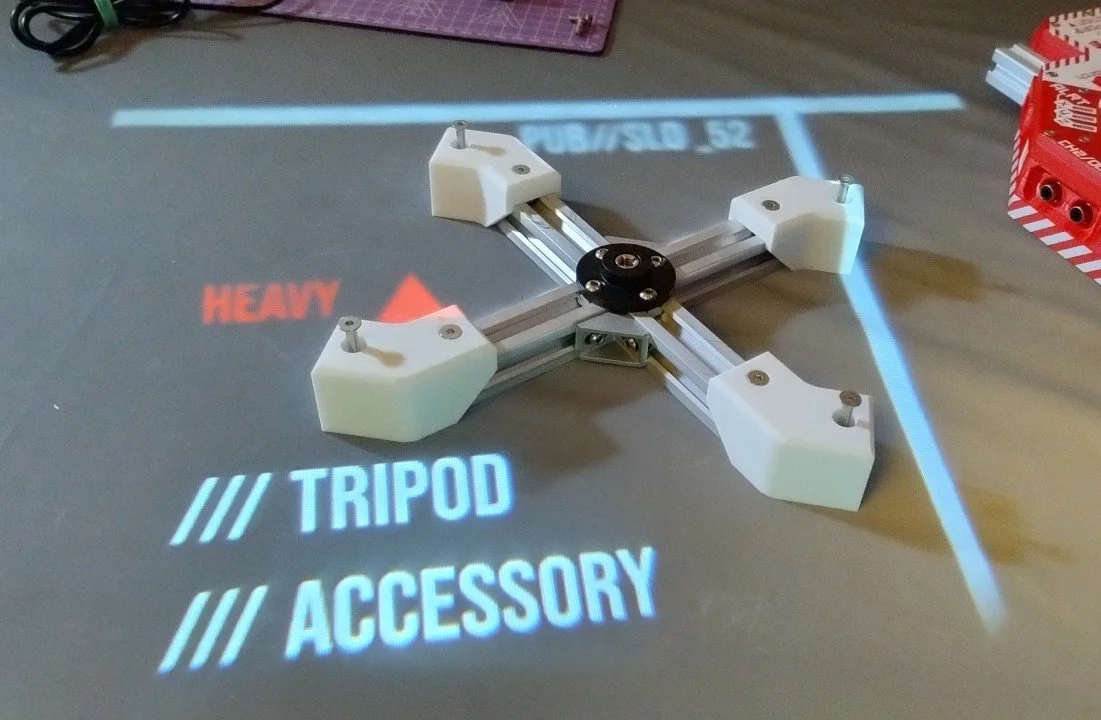
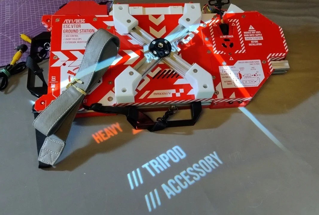
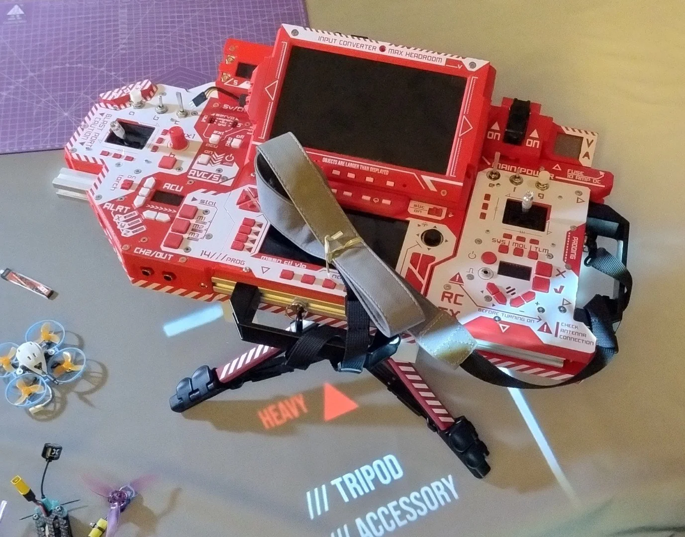
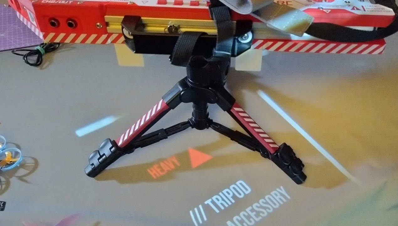
With the unit weighing north of 3 kg in basic configuration, the operator might want a portable mount in the field. There's a gadget exactly for that. It will lift up your game even more.
Obviously the user must ensure the tripod can hold both the deck and the operator's upper body when they lean on the controls — dropping the thing armature-first on your kneecaps is far from fun.
Behind The Panels
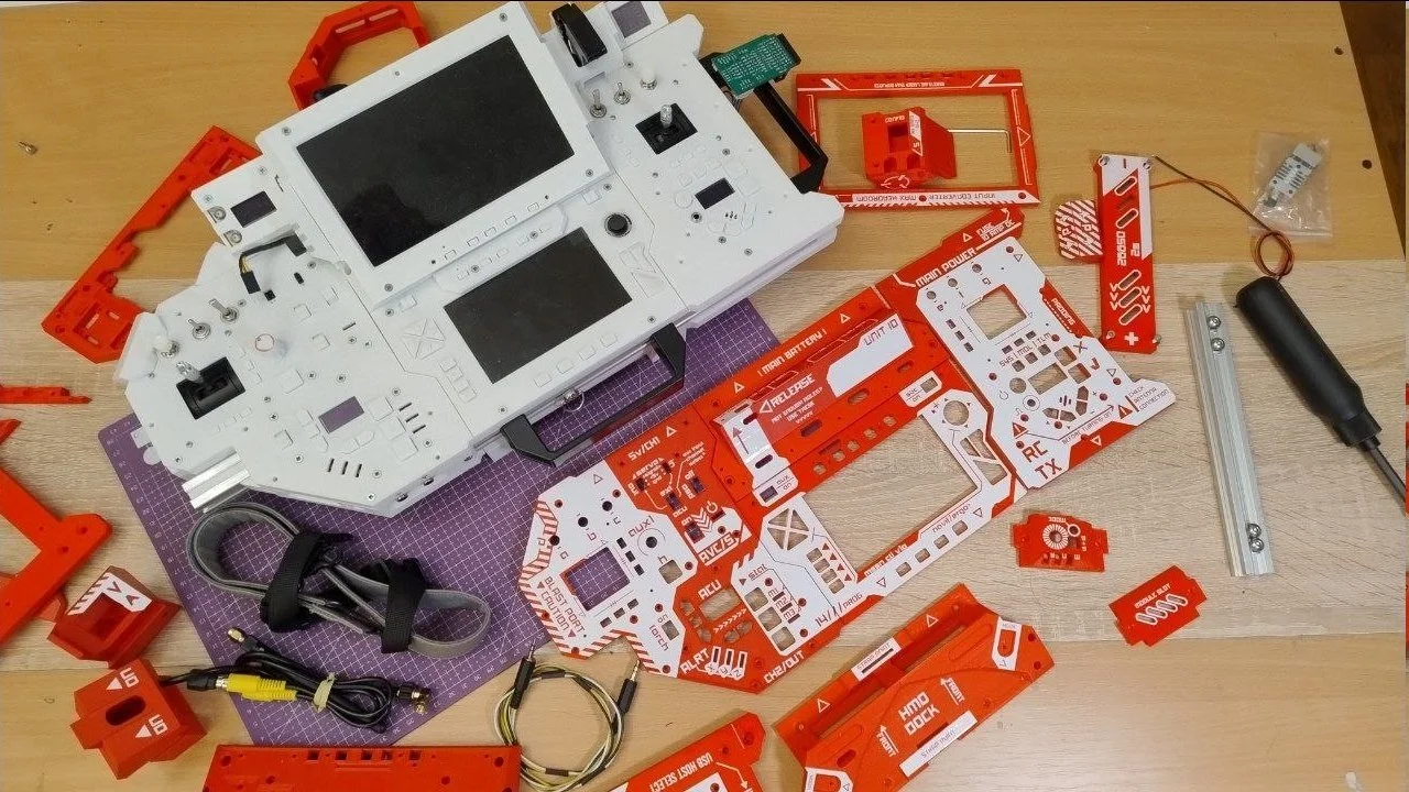
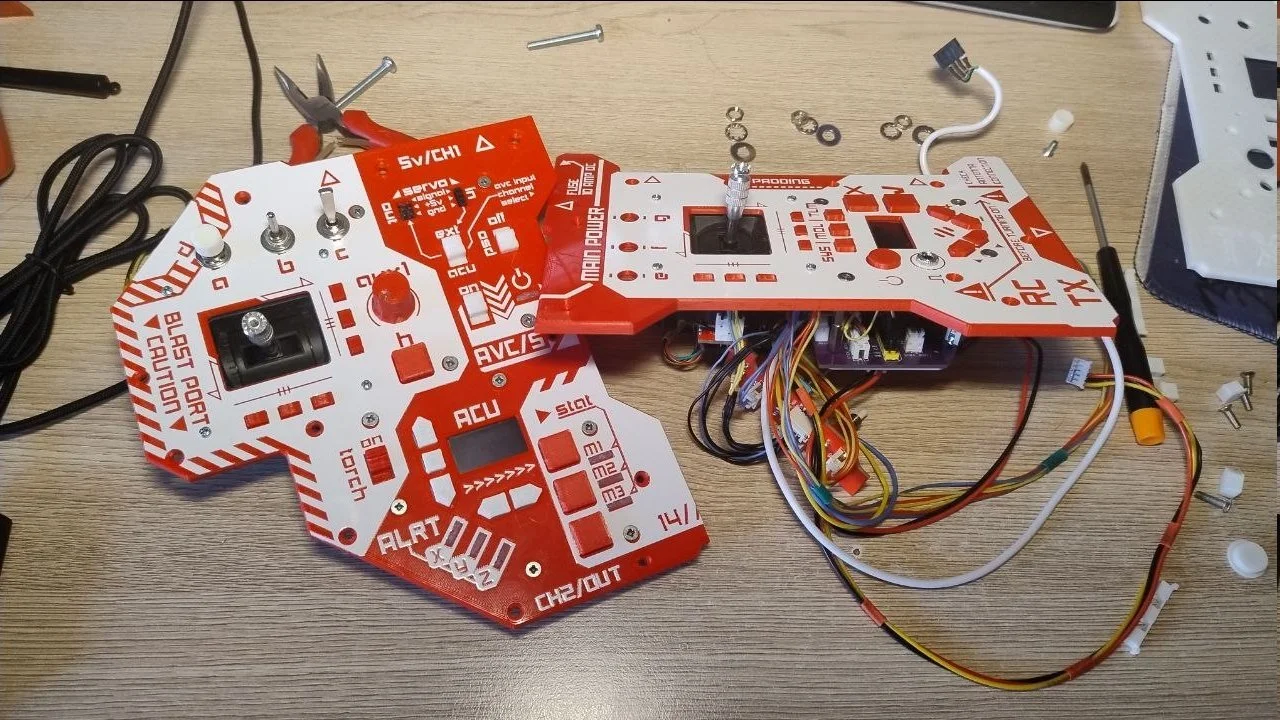
Take a peek behind the scenes. The pre-final prototype case was actually white, before its transformation into Sucrose Shock Scheme.
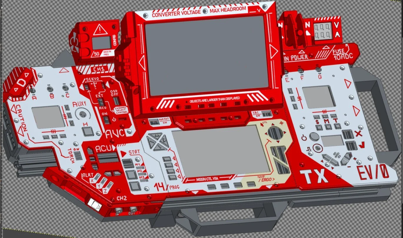
Here's a combined render with some decal work sketched out in GIMP. And no — weird button positioning is not because this image was generated with an LLM. It's just how a 2D editor lays out stuff when you don't carve out every detail.
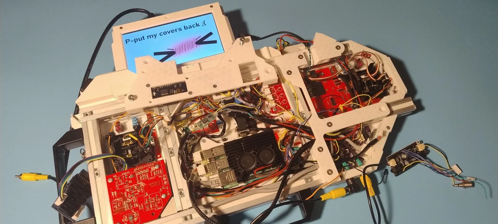
One can guess there are many things that make the deck tick — and even more that link those things together.
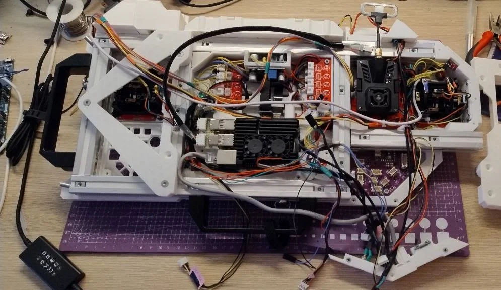
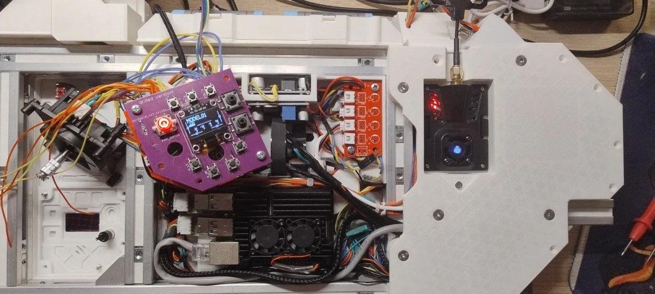
The main SBC, the tried and tested Raspberry Pi 4, sits neatly under the main display with airflow over and under. Nearby, a 4-port USB hub board manages half the deck's inputs — including ETX, the primary input processor, and one external USB connector.
Among the wires and flat cables lives the power conversion and distribution assembly: splitter boards and DC/DC modules. One module starts by default; the other is switch-controlled to shut down the main display, RPi, and USB loads — except ETX, which rides a separate rail.
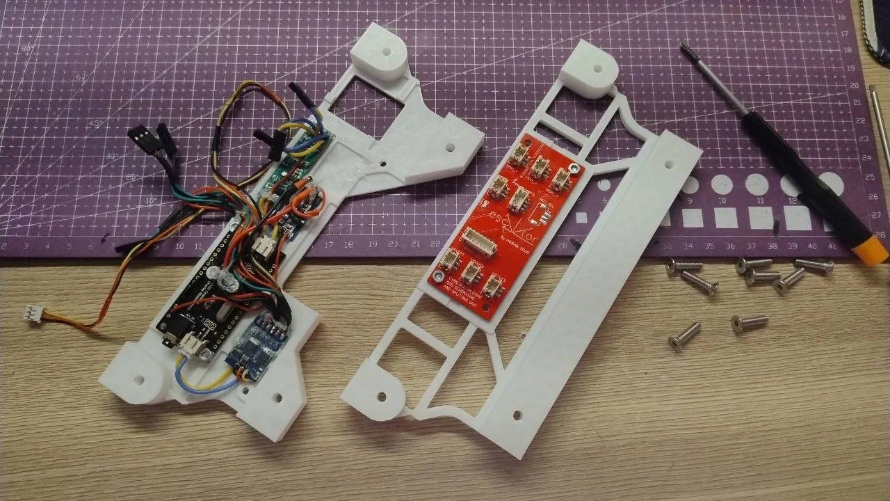
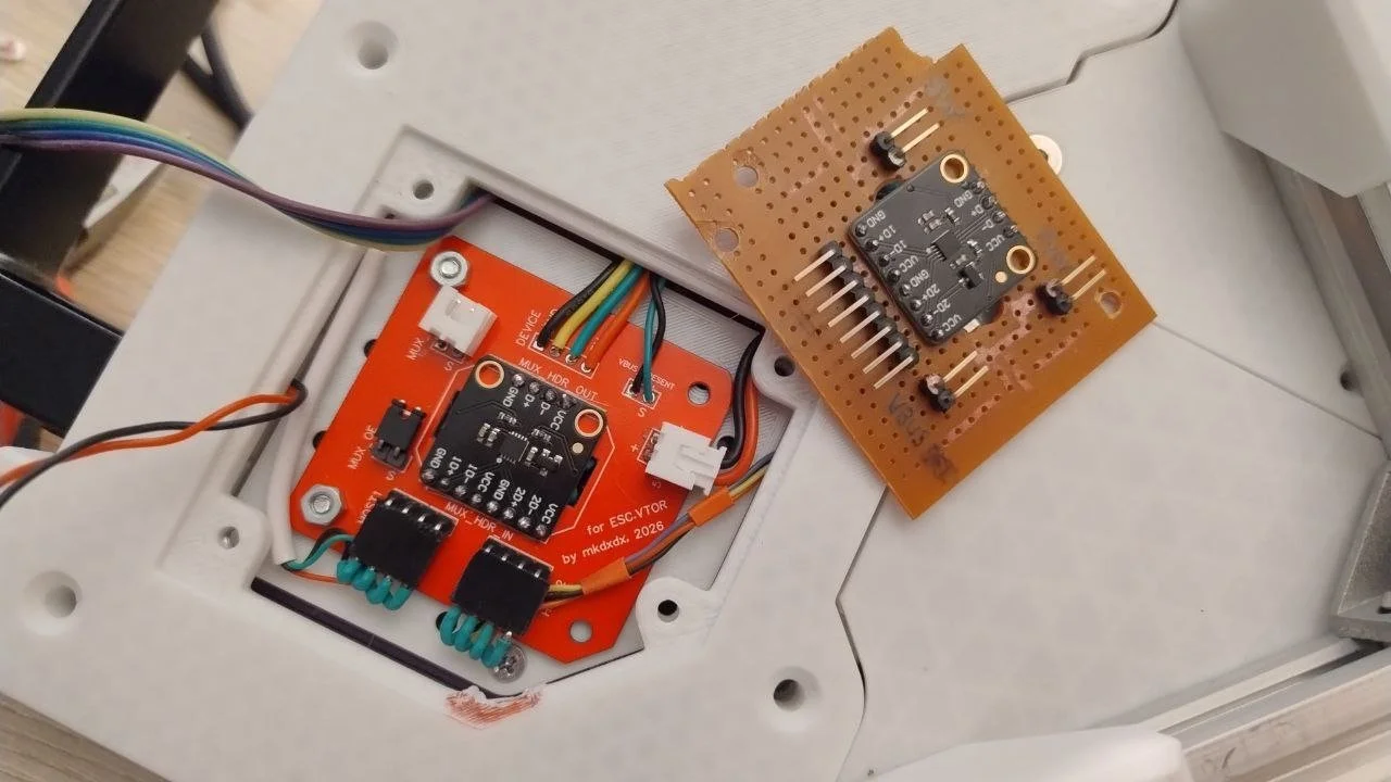
That compact red board is video selection, OSD generation, and splitting. Two I/O pairs go to external connectors; the third output can stay free, or feed what the next board suggests…
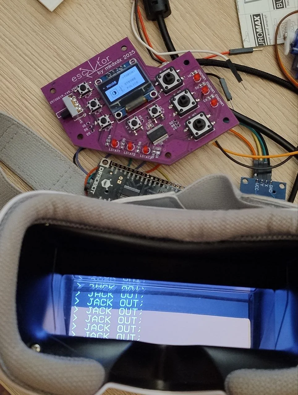
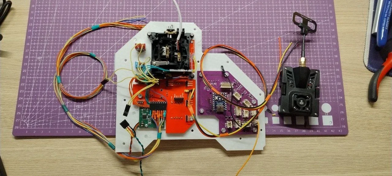
OSD control lands on the same board as primary input processing, RGB blasting, and digital servo-signal generation. Lots of wires to button boards — a big 4×6 key matrix including on-board interface keys — polled by an RP2040 Zero via MCP23S17 I/O expander. That RP2040 also talks to the SBC for input.
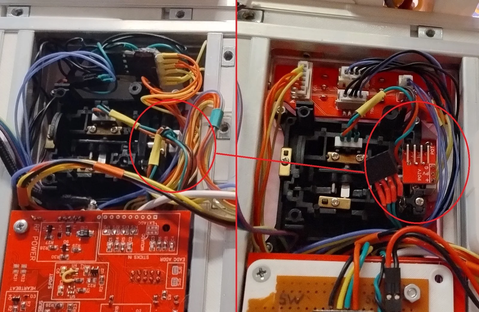
On the other side of the throttle stick: the board that powers the video chain, selects which servo signal hits the multiplexer, and whether to suppress OSD. Transmitter header, auxiliary pot, and button live here too.
The radio controller is a sandwich of boards with an STM32H5 minimal system module in between — Edge-TX port made for this configuration. Switches and buttons sit on their own PCBs to tidy the harness.
Top of the sandwich: USB connection selector — TS3USB221 mux, Schottky diodes on VBUS, USB-C, and a slider to choose SBC vs external host.
The battery pack can be disassembled too.
Build by mkdxdx
Source: https://bitbucket.org/mkdxdx/rasterized/src/master/
Rise above the electric smog, cowboy.